Talking about the fascinations that drive my practice and demonstrating some of the mechanical, electronic and software elements I use in my work. Materials from this talk can be found via my blog.
Author: admin
Music machines
Continuing with LEGO Technic musical work, I will be presenting a kinetic participatory piece that allows the audience to playfully engage with rhythm, activating counter-rhythms in improvisation. Running until the 24th June.
It’s great having a uni workshop to hand. 9am today: a crude layout in masking tape on my carpet; 1pm today: table finished!
This is the main frame for my new LEGO piece ‘Ride with Me’ which will be showing at the BEAM Festival in June. This was a good day for learning as Derek at Brookes let me loose on the power tools.
Drum machine circuit rework
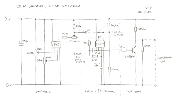
Latest schematic after trying to reduce distortion in the circuit. I’ve added a volume control, proper biasing of signals from the AtTiny, an active 2-pole filter which gives a really clean output, and a massively minimised output stage which is good enough for testing with headphones. My analogue electronics is hit and miss so these values have been found experimentally.
The volume control is part of the biasing circuit. In previous circuits I was saturating the PWM signal into the op amp causing it to clamp to it’s full possible range. This was great in theory but in practice working at full range caused distortion at the limits; there was noise on the top and flattening out of the signal at low frequencies.
With the circuit operating at 5v the new biased signal going into and coming out of the TL072 is between 1.5v and 3v, giving enough tolerance for a clean signal. This is enough voltage to drive the transistor directly, so it runs unbaised with a 10k resistor to convert this to a base current. The component values are borrowed from this excellent three transistor headphone amp.
The low pass filter part is taken from this excellent example. It might be cutting off the high frequencies a little too soon but I’ve left this in so the high sounds are not too piercing. The nice part about this configuration is that’s a neat footprint on protoboard/breadboard as the two caps sit neatly right next to the op amp (15nF going left from pin 2, 33nF going right from pin 3). This is more a note-to-self for breadboarding future versions, and also why I’ve drawn the circuit including the chip pinouts.
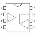
Also as a note to self is this great PDF on biasing op amps, a ridiculously thorough PDF from Texas Instruments (mostly massively out of my league) and a pinout of the trusty TL072:
This machine is a prototype for a concept ‘rhythm piano’ I started designing during my MA which allows a performer to play beat equivalents of tonal ratios. It forces you to compose using rhythm rather than pitch which is a very exploratory process. Feeling your way around the counter-rhythms allows you to discover unusual structures in swing and syncopation, whilst ensuring everything is easily reproducible.
AVR cheap bass drum synthesis
The idea with the drum synth is to get a wide range of sounds out of the smallest, simplest possible circuit. There are 4 drum modes, bass, snare, hat and something more glitchy. I’m using an AtTiny45 as it’s got analogue inputs, fast PWM for output and enough memory for a few lookup tables of data. Here’s the test circuit:
The AtTiny chip is computing each sample at roughly 31kHz so I need to avoid any CPU-hungry operations like multiplication (8Mhz clock/31.25kHz = 256 instructions max). The bass drum gets around this by using two 8 bit lookup tables, each 256 bytes in size. The first is an ‘impact’ table which is a sort of exponential drop off curve and the second is a sine wave scaled to a 0-255 range. Source code is here (Compiled in g++, fuses L = 0xE2, H = 0xDF, E = 0xFF) and here’s the bit that does the important work:
impactPos += speed;
sinePos += pgm_read_byte(&impact_tbl[(impactPos >> 8) & 0xff]);
sample = pgm_read_byte(&sine_tbl[(sinePos >> 4) & 0xff]);
The sine table is being modulated by the ever-decreasing impact table so the frequency drops over time. The speed of the playback determines the pitch of the drum and the initial impactPos determines the type of sound. For a cheesy 70’s disco tom you set it to zero to go from a really high tone down to a low one. For a tech bass you start further down the curve to get a more muted and constrained sound.
This is a lazy approach as there is no decay on the volume – instead it depends on the drum playing out until the frequency of the sine wave is too low to hear. This avoids any multiplications but has some 8 bit artefacts as a consequence (I kind of like them). Here’s some example output:
AVR filtered noise
A cheap LSFR gives a simple white noise output:
//--------------------------------------------------------------------------------
// Fast pseudo random number generator from
// http://en.wikipedia.org/wiki/Linear_feedback_shift_register
//--------------------------------------------------------------------------------
uint16_t g_rand = 0xACE1u;
void nextRand()
{
  g_rand = (g_rand >> 1) ^ (-(g_rand & 1u) & 0xB400u);
}
I want the effect of filter sweeping this but being a little 8 bit chip, proper DSP is out of my league. Instead I do a cheap low pass filter by averaging the last sample with the current one, then the previous one to that with its previous etc. To get more variation I average every other one and then fill the gaps, generates a sort of noise drop off curve:
#define FILTER_NOISE(idx1, idx2)    g_noise[idx1] = (g_noise[idx1] >> 1) + (g_noise[idx2] >> 1);
#define AVG_NOISE(idx1, idx2, idx3) g_noise[idx1] = (g_noise[idx2] >> 1) + (g_noise[idx3] >> 1);

uint8_t g_noise[16];
void updateNoise()
{
  nextRand();
  g_noise[0] = (uint8_t)g_rand; // ** Initial white noise value
  FILTER_NOISE(2, 0)    // Average every other sample to
  FILTER_NOISE(4, 2)    // get more muffled low pass white
  FILTER_NOISE(6, 4)    // noise.
  FILTER_NOISE(8, 6)
  FILTER_NOISE(10, 8)
  FILTER_NOISE(12, 10)  // Last couple of sample are filtering
  FILTER_NOISE(13, 12)  // each sample.
  FILTER_NOISE(14, 13)
  FILTER_NOISE(15, 14)
  AVG_NOISE(1, 0, 2)    // Averate between gaps in filtered
  AVG_NOISE(3, 2, 4)    // samples.
  AVG_NOISE(5, 4, 6)
  AVG_NOISE(7, 6, 8)
  AVG_NOISE(9, 8, 10)
  AVG_NOISE(11, 10, 12)
}
Messy code, but still faster than my awful assembly code version… beaten by GCC’s optimiser once again. Here’s what it sounds like sweeping over this with a pot:
[audio:https://www.alexallmont.com/wp-content/uploads/2012/04/noise-capture.mp3|titles=noise capture]Drum synth fast PWM
An update whilst getting the drum synth code together. The output is 8 bit at 31.25kHz, a frequency derived from the 8Mhz clock speed divided by 256 – the number of clock cycles it takes for the PWM ramp to go full cycle.
Interrupt initialisation including analogue input for potentiometers and piezo:
int main(void)
{
  // PWM output on PORTB0 = pin 5.
  DDRB = _BV(0);

  // PWM init, 8Mhz / 256 gives 31.25kHz
  TCCR0A =
    _BV(COM0A1) |           // Clear OC0A/OC0B on Compare Match.
    _BV(WGM00) |_BV(WGM01); // Fast PWM, top 0xff, update OCR at bottom.
  TCCR0B = _BV(CS00);       // No prescaling, full 8MHz operation.
  TIMSK = _BV(OCIE0A);      // Timer/Counter0 Output Compare Match A Interrupt Enable

  // Analogue init.
  ADCSRA |=
    _BV(ADEN) |              // ADC Enable
    _BV(ADPS1) | _BV(ADPS0); // Div 8 prescaler

  // Enable interrupts.
  sei();

  // Main loop.
  for (;;)
  {
    // ** Get user input **
  }
}
ISR sample update code, the sample is set as the PWM output, the sample update code sets it for the next time around:
uint8_t g_sample = 0;
ISR(TIM0_COMPA_vect)
{
  // 8 bit playback at 31.25kHz.
  OCR0A = g_sample;
  // ** Sample update code here **
}
Not the most cutting edge audio player, 8 bit and no fast buffering of any kind but good enough for now. The sample generation code is tricker than expected; using an ATTINY45 means that efficient multiplication is not an option I’m in bit-hacking domain.
First Drum Synth Build
The drum runs from 5v but for project completeness sake I put it in a box with a 9v battery. The leftmost two pots control sound parameters with the third controlling volume. The piezo picks up finger impacts from the outside so you can play the drum by tapping the tin. From left to right the circuit goes: 9v to 5v regulator, ATTINY45 synth (with a header around chip for in-circuit programming), filtering & pre-amp, power amp.
Circuits always seem to end up denser when I actually build them – it was a cram getting all this onto protoboard. The actual circuit is pretty neat but the rats’ nest of cables is from hooking everything up to switches. I also had to shoehorn more caps in than expected. It would have been wiser to choose a bigger box and measure/mark out all the controls rather than faff around with files and a hole-borer, but I learned a lot for the next build in the process. Notably: I’ve never experienced dry solder joints before but the analogue stage of this circuit really highlighted them, I’m used to using strip board and not this sort of protoboard so I need a bit of practice here; the piezo does all manner of weird stuff when the metal side is against the inside of the tin, grounding issues; the whole circuit could be shuffled to the right – squeezing the battery in was a relatively last-minute decision.
Paint job required. I’m still running this with the original software from my rhythm piano and I want to add more range to the sounds. The next post will have the first ‘official’ code release in which I’d like to include some lovely abrasive glitchcore modes I discovered whilst this circuit was playing up.
Procrastination Rag
Somewhere between putting off finishing my drum synth and lunchtime, a wave of bank holiday procrastination came manifest as rag:
[audio:https://www.alexallmont.com/blog/wp-content/uploads/2012/04/R09_0010.mp3]Chords: G, B7, E, E7, A7, D9(?), G. Also half speed G7, C, A7, D (slide up to 7th)
What ever D9(?) is, it’s the chord that opens Clapton’s version of Hard Times with a bit of extra pinkie action x54557.


